How to mod your TS10
Before you start
Unlike its TS5 and TS9 siblings, the TS10 requires a grocery list of changes to bring it up to TS808 specs. Actually it's more like to bring it down to TS808 specs. The TS10 has a lot of extra circuitry that you will be removing and bypassing to dumb it down. With that said, let's get to it.
First take it apart!
You'll need to pull the 3 knobs (drive, tone, level) off. They should come off fairly easily. Each knob has a collar, so watch for it if the knob pops off quickly.
Next remove the 4 Phillips screws holding the base on. Remove the base and the black plastic shield under it. This will reveal the main circuit board held on by one Phillips screw. Remove the Phillips screw. The main circuit board is now free to slide out with a little coaxing. Underneath the main circuit board is a smaller circuit board connected to the main one by a ribbon wire. Remove the 4 Phillips screws holding the smaller circuit board in place. Wiggle the smaller circuit board out as well. You won't be making any any modifications to the smaller circuit board; it is just much easier to work on the main board with the smaller one removed.
Identify the components!
The TS10 components are all marked so it is very easy to identify which parts to change. Each component has a reference number: R1 for resistor number 1, C1 for capacitor number 1, etc. Locate the components using the following component reference numbers and refer to the TS10 circuit board pictures below (the wire ribbon has been cut and pasted out of the pictures). Since there are a lot of changes to make they have been grouped into sections:
Section One
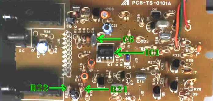
IC1 - this is typically the MC4558 op amp chip which you will replace with the 8 pin socket and JRC4558D op amp chip. Note: a good number of TS10's came with the JRC4558D op amp chip. If yours already has this chip, leave it in there!!!
R21 - this is the 470 ohm (yellow-purple-brown-gold) resistor that you will replace with the carbon comp 100 ohm (brown-black-brown-gold) resistor.
R22 - this is the 100K ohm (brown-black-yellow-gold) resistor that you will replace with the carbon comp 10K ohm (brown-black-orange-gold) resistor.
C6 (optional) - this is the .047uF capacitor (usually a silver 'chiclet' type marked 473K) which you will replace with the poly film .1uF capacitor (usually a green or yellowish/greenish 'chiclet' type often marked 104K).
TS10 circuit board picture for Section One (pre-mods)
Section Two
R39 - this is a 1K ohm (brown-black-red-gold) resistor which you will remove.
R40 - this is a 10K ohm (brown-black-orange-gold) resistor which you will remove.
Q6 - this is a C1815 (black) transistor which you will remove.
R39 O side to R40 O side - these are the now empty circuit holes which you will jump with a portion of the shielded wire provided.
R26 - this is a 10K ohm (brown-black-orange-gold) resistor which you will replace with the 39K ohm (orange-white-orange-gold) carbon film resistor.
R27 - this is a 22K ohm (red-red-orange-gold) resistor which you will replace with the 56K ohm (green-blue-orange-gold) carbon film resistor.
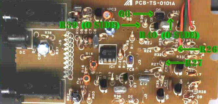
TS10 circuit board picture for Section Two (pre-mods)
Notes:
R39 O side and R40 O side mean the circuit hole that has the O (circle) around it.
Section Three
R2 - this is a 9.7K ohm (white-purple-red-gold) resistor which you will remove.
R3 - this is a 22K ohm (red-red-orange-gold) resistor which you will remove.
R3 O side to J5 5 side - this is a now empty circuit hole which you will jump to an occupied circuit hole using a portion of the shielded wire provided. This is the only circuit board solder side jumper that you will make.
C2 - this is a 10uF (black electrolytic) capacitor which you will remove (you should be able to leave it in, since it shouldn't be connected to anything anymore, but I always remove it just in case).
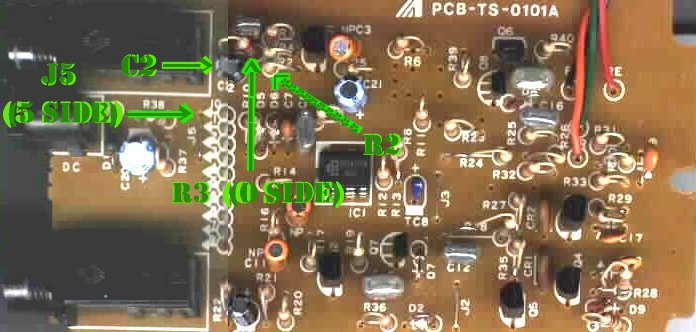
TS10 circuit board picture for Section Three (pre-mods)
Notes:
As before, R3 O side means the circuit hole that has the O (circle) around it. J5 5 side means the circuit hole that is closest to the "5" in the J5 marking.
Also, I found it easiest to jumper R3 O side to J5 5 side on the other side of the board. If you find it easier to do it another way, go for it!
Section Four
R6 - this is a 220 ohm (red-red-brown-gold) resistor which you will remove and then jumper the empty circuit holes with the bare wire provided.
C11 - this is a 1uF (orange electrolytic) capacitor which you will remove and then jumper the empty circuit holes with the bare wire provided.
R17 - this is a 510K (green-brown-yellow-gold) resistor which you will remove.
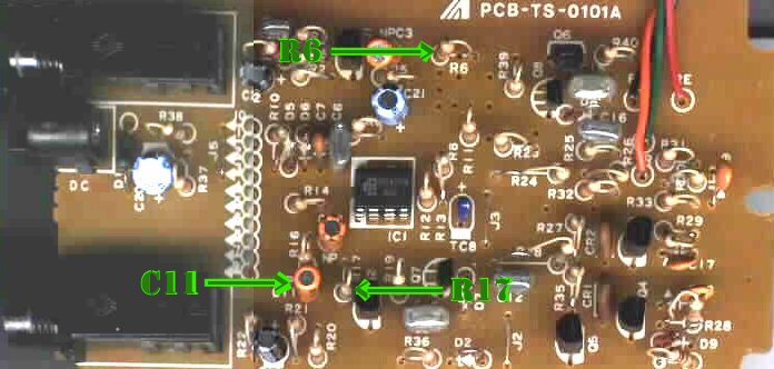
TS10 circuit board picture for Section Four (pre-mods)
The 3 first three component changes in Section One (IC1, R21, R22) are generally referred to as the TS808 mod. Using carbon comp resistors along with the capacitor change (R21, R22, C6) is sometimes referred to as the brown mod. You could go out and get carbon comps and change all the resistors, but changing these 2 are supposed to give the most bang for the buck. The capacitor change is listed as optional since this change is not part of the original TS808 spec. It gives the box more bass. Maybe you want more bass or maybe you don't. I personally like the extra bass and am guessing the majority of you will too.
You may want to try one section at a time to see what suits your tastes. Sections two through four bypass extra circuitry not found in the TS808, TS9 and TS5. The changes to resistors R26 and R27 in section two get rid of the 'squawk' or 'chirp' problem commonly encountered in TS10 to 808 conversions. Sections one and two will make the most noticeable difference, so I suggest you do at least those two.
Get out the soldering iron!
Get a de-soldering bulb. Or use a de-soldering braid if you are handy with that. If you can, secure the circuit board so you can use both hands. Get as much solder off the leads of all the components you plan to change. Caution: Do not try to bend or push the component leads without the solder in a melted state! The copper on the circuit board separates from the board and will tear off very easily (take it from someone who has done it!). I suggest you try to push the component leads through using the soldering tip itself, and then use tweezers or needle-nose pliers at the same time to help wiggle it through. The chip is toughest to get out. Make sure you note the orientation of the chip before you free it from the board.
Installing the new components is much easier than taking off the old ones. Make sure all the holes are free of solder so that the components leads can slide fairly easily into them. If you force them through, you run the risk of separating the copper from the board and tearing it.
The new capacitor is much bigger than the one it is replacing. Just pull both leads through as far as you can and press the capacitor down a bit so it sits close to the board. Solder everything up and clip the extra lead lengths down close to the board.
Make sure you are grounded before touching the chip, or at least recently grounded (remember touching something metallic after rubbing your feet on the carpet when you were a kid?). Static electricity can ruin a perfectly good chip. Hopefully you noted the orientation of the old chip because the new one most be oriented the same way or it will blow immediately when you turn it on. Refer to the TS10 circuit board picture if needed. There is a notch in the chip that should face the middle of the board, and the lettering on the chip should read the same direction as some of the component reference numbers, like R9 right above it and IC1 right below it. To plug it into the socket, line up 4 of the leads on one side first, then the other 4. Once you are confident that the leads are lined up start pushing it in place. Be careful not to bend any of the pins.
Test it out!
Before you put it back together, try it out. Make sure the board is not sitting on anything metallic like an amp corner or handle. If it doesn't work, here are some checkpoints:
- make sure the battery is hooked up and is not dead
- make sure the battery lead is not damaged
- check all the solder jobs for cold solder joints or spillover
- check chip orientation
https://deadfoot.tripod.com/modts10.html
https://deadfoot.tripod.com/modts10a.jpg
https://deadfoot.tripod.com/modts10b.jpg
https://deadfoot.tripod.com/modts10c.jpg